|
JayAudio
|
|
|
Group: Forum Members
Posts: 5,
Visits: 26
|
+xHi Jay, Thanks for posting further information. Yes, I think I understand what you're getting at. First of all I'll say that multicores, currently, are not supported ideally and there is not a 'multicore object' as such. Improved multicore support is something we're looking to cater for in a future version, and that may well be the answer to your queries. Perhaps, also, what follows may well help explain why things are the way they are. The design and conceptualization of Block Schematics in Stardraw Design 7 has evolved, so far, with these principles in mind: 1) It is a logical view, not specifically a 'physical' view, of connections between products. 2) It focusses on discreet signal levels, not the individual core/pin level. What I mean by this is that Stardraw Design 7's design for Block Schematics expects the user to show, for example, a balanced audio signal as a single coherent path, or Cable, but does not expect to show, in most cases, the individual hot, cold and screen cores in the foil screened twin cable (although you can, of course, do this). So perhaps that's the disconnect between what you're experiencing and what, ideally, you'd like to see. Unlike the PCB and wire examples you mention, Stardraw's Block Schematics generally show that this audio, or video, or control, or data, or network, or power signal go from this thing to that thing, rather than that the blue core goes from here to here, while the blue/white core goes from there to there, while the orange core goes this way, and so on. To restate, then, the imagined use case is that people are, on the whole, documenting logical signal paths rather than physical core paths. I hope that makes some sort of sense. Going further, then, the Pictorial Schematics Module is an ultra-high level view which is along the lines of 'this thing connects to that thing' while Block Schematics shows 'this signal path runs from this device to that device(s)' while maybe what you're seeking is a view that demonstrates 'this core runs from this physical point/pin to that physical point/pin'. But overall i think we're more or less on the same page; most of what you want to do you can do today, and we hope to introduce an amazing multicore tool in due course. As to connecting Cables - we consider everything our licensees suggest and prioritize development based on what the market wants and what features deliver the most 'bang for buck', so nothing should be ruled out. Regarding your follow up question about auto-updating changed products, there isn't a project- or drawing-wide auto-updater, but there is an accelerator: delete the UDP symbol in the drawing, it will return to the Available Symbols Palette, and when you drag that product back out of the Available Symbols Palette it will use the new UDP symbol to which you've made changes. I hope this is helpful. Thank you Rob that was awesome :-)
|
|
|
|
|
Rob Robinson
|
|
|
Group: Administrators
Posts: 2.3K,
Visits: 9.1K
|
Hi Jay,
Thanks for posting further information. Yes, I think I understand what you're getting at.
First of all I'll say that multicores, currently, are not supported ideally and there is not a 'multicore object' as such. Improved multicore support is something we're looking to cater for in a future version, and that may well be the answer to your queries. Perhaps, also, what follows may well help explain why things are the way they are.
The design and conceptualization of Block Schematics in Stardraw Design 7 has evolved, so far, with these principles in mind:
1) It is a logical view, not specifically a 'physical' view, of connections between products.
2) It focusses on discreet signal levels, not the individual core/pin level. What I mean by this is that Stardraw Design 7's design for Block Schematics expects the user to show, for example, a balanced audio signal as a single coherent path, or Cable, but does not expect to show, in most cases, the individual hot, cold and screen cores in the foil screened twin cable (although you can, of course, do this).
So perhaps that's the disconnect between what you're experiencing and what, ideally, you'd like to see. Unlike the PCB and wire examples you mention, Stardraw's Block Schematics generally show that this audio, or video, or control, or data, or network, or power signal go from this thing to that thing, rather than that the blue core goes from here to here, while the blue/white core goes from there to there, while the orange core goes this way, and so on.
To restate, then, the imagined use case is that people are, on the whole, documenting logical signal paths rather than physical core paths.
I hope that makes some sort of sense.
Going further, then, the Pictorial Schematics Module is an ultra-high level view which is along the lines of 'this thing connects to that thing' while Block Schematics shows 'this signal path runs from this device to that device(s)' while maybe what you're seeking is a view that demonstrates 'this core runs from this physical point/pin to that physical point/pin'.
But overall i think we're more or less on the same page; most of what you want to do you can do today, and we hope to introduce an amazing multicore tool in due course. As to connecting Cables - we consider everything our licensees suggest and prioritize development based on what the market wants and what features deliver the most 'bang for buck', so nothing should be ruled out.
Regarding your follow up question about auto-updating changed products, there isn't a project- or drawing-wide auto-updater, but there is an accelerator: delete the UDP symbol in the drawing, it will return to the Available Symbols Palette, and when you drag that product back out of the Available Symbols Palette it will use the new UDP symbol to which you've made changes.
I hope this is helpful.
Kind regards,
Rob Robinson
Stardraw.com
|
|
|
|
|
JayAudio
|
|
|
Group: Forum Members
Posts: 5,
Visits: 26
|
+xHi Jay, I disagree that cables should connect to cables. Conceptually and architecturally a cable connects one product to another, so that is how Cables are designed to connect. Stardraw Design 7.3 is not just about rough visualization but deals with the logical connection between the devices in your system and in this way it can produce advanced output like Cable Schedules. To do this, though, your Cable needs to connect Product A to Product B directly. How it looks is entirely up to you, though, so you can overlap Cables, and you can add a circle or dot or whatever other graphical element you want so that it looks like one Cable connects to another, even though logically and in terms of signal flow this is not the case, and this gives you the flexibility to represent interconnections any way you want. Internally, also, and by definition/design, connection points are created programmatically when the Symbol being inserted into a drawing has a cyan IO stub. No cyan stub, no connection point. If you're worried about seeing these stubs, don't be: a) the connecting Cable should overlay and therefore hide the stub and b) you can use View | Hide Stubs to disable rendering of the IO stubs. While we appreciate suggestions for new functionality, at this early stage in your exposure to the application it might be best to explore how to achieve your particular objectives with what exists today rather than assuming a new feature is the only way to do what you want; things are generally the way they are for good reason, and over the years and many iterations of Stardraw many, many features have been developed that allow most people to do what they need to get done. I hope this makes sense. Also Is there a way to auto update the products you have made changes to?
|
|
|
|
|
JayAudio
|
|
|
Group: Forum Members
Posts: 5,
Visits: 26
|
+xHi Jay, I disagree that cables should connect to cables. Conceptually and architecturally a cable connects one product to another, so that is how Cables are designed to connect. Stardraw Design 7.3 is not just about rough visualization but deals with the logical connection between the devices in your system and in this way it can produce advanced output like Cable Schedules. To do this, though, your Cable needs to connect Product A to Product B directly. How it looks is entirely up to you, though, so you can overlap Cables, and you can add a circle or dot or whatever other graphical element you want so that it looks like one Cable connects to another, even though logically and in terms of signal flow this is not the case, and this gives you the flexibility to represent interconnections any way you want. Internally, also, and by definition/design, connection points are created programmatically when the Symbol being inserted into a drawing has a cyan IO stub. No cyan stub, no connection point. If you're worried about seeing these stubs, don't be: a) the connecting Cable should overlay and therefore hide the stub and b) you can use View | Hide Stubs to disable rendering of the IO stubs. While we appreciate suggestions for new functionality, at this early stage in your exposure to the application it might be best to explore how to achieve your particular objectives with what exists today rather than assuming a new feature is the only way to do what you want; things are generally the way they are for good reason, and over the years and many iterations of Stardraw many, many features have been developed that allow most people to do what they need to get done. I hope this makes sense. So you disagree that in a software application that the cable should not join to itself....so if I don't make it to the other product I have to add nodes and extend the cable, instead of just clicking at the end of the cable and continuing the line (Cable) . Also if I have a multi-core cable, but each end goes somewhere different you also disagree that it would be easier if you could get to a point and say now I want six ends coming off that one line? I get that its easier if you are going point to point, however in some instances this is not the case, such as connecting a diode from one wire/cabe/line to another wire/cabe/line. Also wires/cables/lines in a practical sense are soldered together all the time, two ends together to make one etc. 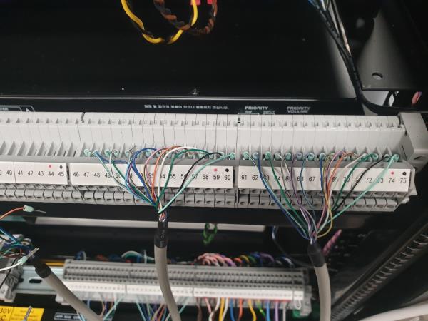 I hope the picture explains what I am getting at. All I wanted to know is it something stardraw would thing of implementing as I am sure there is many more people asking the same question....i.e do i really need to go left to right 30 times to the same connection but 30 different end connections. I am just thinking of an easier way. and showing that two cables are connected to each other. I get that I am asking for something strange, and doted nodes are more a PCB design feature however wire is wire and copper plate on a PCB is PCB wire connecting the components together this is the same just not at component level. Again this is not a personally I etc etc. this is about the end user asking about a possible update to incorporate a feature or even a cable preset that connects to its self, and can add visually seen Nodes, and to signify these two cables are joined together. and I know you was being very diplomatic with how long I have been using the software etc....I had used it throughout the day continuously and have been since my registration for the 30 day trail. I am now coming up to about two weeks plus this is not the first time I am using this kind of software, I have taken every thing you said on board, however I still feel that this function would be very beneficial, as in software and reality there is always physical and application differences. Thank you again for your time, sorry I am being a pain. Again the more Lines/wire/cable you have to connect point to point the more complex the schematic will be, this is fine for users such as my self, however some of our clients, installation engineers from other companies don't all have this overall knowledge., or when looking at this very detailed lines/cables/wire feel over encumbered by how many lines/cables/wires there are.
|
|
|
|
|
Rob Robinson
|
|
|
Group: Administrators
Posts: 2.3K,
Visits: 9.1K
|
Hi Jay,
I disagree that cables should connect to cables. Conceptually and architecturally a cable connects one product to another, so that is how Cables are designed to connect. Stardraw Design 7.3 is not just about rough visualization but deals with the logical connection between the devices in your system and in this way it can produce advanced output like Cable Schedules. To do this, though, your Cable needs to connect Product A to Product B directly.
How it looks is entirely up to you, though, so you can overlap Cables, and you can add a circle or dot or whatever other graphical element you want so that it looks like one Cable connects to another, even though logically and in terms of signal flow this is not the case, and this gives you the flexibility to represent interconnections any way you want.
Internally, also, and by definition/design, connection points are created programmatically when the Symbol being inserted into a drawing has a cyan IO stub. No cyan stub, no connection point. If you're worried about seeing these stubs, don't be: a) the connecting Cable should overlay and therefore hide the stub and b) you can use View | Hide Stubs to disable rendering of the IO stubs.
While we appreciate suggestions for new functionality, at this early stage in your exposure to the application it might be best to explore how to achieve your particular objectives with what exists today rather than assuming a new feature is the only way to do what you want; things are generally the way they are for good reason, and over the years and many iterations of Stardraw many, many features have been developed that allow most people to do what they need to get done. I hope this makes sense.
Kind regards,
Rob Robinson
Stardraw.com
|
|
|
|
|
JayAudio
|
|
|
Group: Forum Members
Posts: 5,
Visits: 26
|
Thank you for getting back to me,
Sometimes working to a grid snap is not always feasible with some designs. And I am only using it roughly things don't need to look that pretty I am more testing functionality not aesthetics although I appreciate where you are approaching the matter from. What I want is the cables to connect together with a dot, the only way I have managed to do this is add the dot myself. And if you check for the diode symbol in the old.pdf connecting a diode to a cable within stardraw is problematic.... i do understand that end to end (connector to connector) it has the ease of workflow however not every situation is the same and this could be resolved by making the cable connectable. Would this be something that stardraw would consider implementing?
Also the Din's do have Stubs they are just really small and it was a bit rushed, such as not aligned.
Symbols is more to do with the selection, obviously there is 1000's I don't expect you to have them all however you don't have a diode.
So recap brief
1- cable connectivity - would stardraw consider adding this
2- terminal connections that don't need a line creating from named stubs
Thank you again rob again sorry to be a pain
|
|
|
|
|
Rob Robinson
|
|
|
Group: Administrators
Posts: 2.3K,
Visits: 9.1K
|
Hi Jay, Thanks for your questions and the inclusion of images etc that illustrate your troubles. I think the root problem is that you've gotten off on the wrong foot and by not using library symbols or standard working practices you've not only lost most of the benefits built into Stardraw Design 7.3, but also created some headaches for yourself, so it's a bit of a double-whammy. Starting with first principles: 1) In the Block Schematic environment, Stardraw's library symbols and the grid are built to work together. IOs in the Symbols sit on gridpoints and Snap to Grid is always on which means that it's easy to draw Cables between IOs that are neat, orthogonal (either horizontal or vertical) and evenly spaced. 2) Workflow: the imagined and expected workflow is that you insert your product symbols first and then, when the symbols you want to connect are present in the drawing, you add Cables between them. This means that each Cable object is contiguous and can be created in a single action - there is no need to connect one Cable to another, so this functionality does not exist (although you can extend an existing Cable by adding nodes). It does not seem like a good workflow to add a symbol, then draw a bit of a cable, stop, add another symbol, draw a second cable from that and then attach this second cable somehow to the first; perhaps I've got it wrong but that seems very inefficient. 3) Products, Symbols and Symbol modification; The architecture of Stardraw Design 7.3 is product based. Your project contains Products, and those Products are represented by Symbols. When you add a product symbol into a drawing what you're really doing is a) adding a Product to your Project and b) representing that Product in the current Drawing with that Symbol. We make the assumption that symbols are accurate i.e. all the IOs are present and correct. Therefore if you find that you need to add IOs then you must be representing a new Product, one with inputs and outputs that are different from those of the current Product. Therefore you should create a User Defined Product (UDP) and use the tools that are available to this subset of functionality to add IOs and whatever you want to your custom symbols. For more on this see the movie "Adding New Products" which is #09 on the Stardraw Design 7.3 movies pageBack to your specific issues: Question 1: it appears that you've started your drawing by adding some graphics that look like, for example, DIN rail terminals. The graphics, however, are not Symbols representing Products, as far as I can tell, so a) SD7.3 doesn't know that they should support connections and b) they do not conform to any kind of symbol standard so don't sit on the grid and it will be hard or impossible, as you've found, to line up Cables neatly. Solution: use Stardraw library symbols or create UDPs with correctly positioned IOs. Question 2 pt1: I'm not sure what you mean by "symbols are a bit limited". Do you mean that the library does not contain the Products you need, in which case see "What can I do if a product is missing from the library?" on the Stardraw Design 7.3 FAQs page, or do you mean that the symbol standard itself does not represent products in a way that you'd like? If the latter, you are free to develop you own symbol standard and apply it to your own UDPs using the freeform Symbol Editor. Question 2 pt2: no, even with a lapsed Subscription you can still use Stardraw Design 7.3 and edit symbols etc. For a full run down on the services provided through the Subscription see our website's Subscriptions page. Question 3: IOs can be added in the Symbol Editor, which is the correct way to do it for the reasons described above, but connections cannot be added to symbols in a drawing or, in the case of your drawing, arbitrary collections of graphics that do not represent a Product in the Project. This is a rule based on the way Stardraw Design 7.3 works from an architectural standpoint. From a technical standpoint you should know also that connection objects (the thing a Cable actually connects to) are created programmatically on-the-fly when a correctly formatted Symbol is inserted into the drawing; there is no possibility for arbitrary user-generated connection points to be created in a drawing. I hope that this makes sense and is helpful. I think it could be of great benefit for you to watch some of the movies on the Stardraw Design 7.3 movies page, particularly #02 Basic Use, #04 Cable Tool and #09 Adding New Products - these should help you restart on the right track and overcome any pre- or mis-conceptions about functionality and workflow that may have hampered your efforts so far.
Kind regards, Rob Robinson Stardraw.com
|
|
|
|
|
JayAudio
|
|
|
Group: Forum Members
Posts: 5,
Visits: 26
|
Hi guys,
I am currently in the 30 day trail. I have a few questions and wish for them to be answered with the technical answers and the not so technical answers.
For this product I decided to evaluate it against a few others. I work for a company and we are looking to upgrade the software.
I have a design plan....block diagram within an old program.....I have printed it off and recreating it within stardraw.
1 - The cable runs are problematic (this is by no means an insult to the program development) I just wish for someone to explain why connecting cable lines together is such an issue.
2 - Symbols are a bit limited and if you was not to renew the subscription service I am guessing you would lose the ability to add stubs to products.
3 Why can we not add just one terminal that has a node to a product? not a line or something like that but a blank hole so to speak that the cable connects to.
I like the program and it has great potential I just see the cable aspect as bit of problem, THIS COULD BE BECAUSE I AM MISS SOMETHING and I am prepared for that to be the case.
Any Help or advice would be greatly appreciated.
I include a picture of what I wish to create and the issues I am having with descriptions. (oh the blue dots is where I would like the cables to connect....why dose it not have connection points or snap to the line unless you want to go past it like underneath)
|
|
|
|