By FTC - 11/21/2024 9:52:18 PM
Hi there,
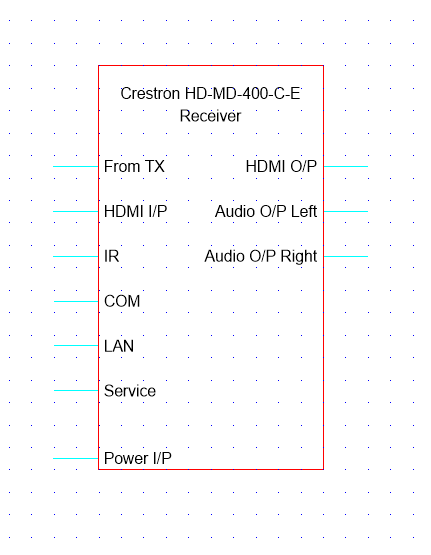
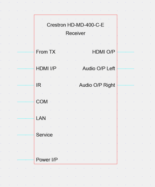
Having an issue with a block where the input output lines aren't lining up with the grid. When viewing the editor for the block, the lines are lined up with the grid but not when adding to a schematic. Unsure how to resolve this?
I've tried all 3 options to align (Top, Middle, Bottom) but doesn't get it lined up.
In the schematic:

In the block editor:

Thanks!
|
By Rob Robinson - 11/21/2024 10:53:35 PM
Hi,
The problem is caused by the fact that your UDP symbol has not been positioned correctly relative to the insertion point, represented by a blue cross in the Symbol Editor. Ideally, a point where an Input stub meets the red outline of the symbol should sit exactly on the blue cross. This point will then align with the cursor when you drag the symbol into a drawing.
If the blue cross is outside the extents of the symbol then the insertion point will default to the center point of the symbol and this can mean that the symbol will not sit on the grid when you drag it into a drawing.
In the Symbol Editor, zoom out until you see the blue cross and then move the symbol so that the inner end of an IO stub sits exactly on the blue cross.
When fixed, delete the symbol from your drawing and then drag it back into the drawing from the Available Symbols Palette and all will be well.
I hope this is helpful.
|
By Adam W - 7/2/2025 10:54:02 PM
I am a new user (obv.) but this is happening with every factory symbol I have used thus far. Do I need to make a custom UDP for every factory symbol? A can add this as first step for the first time I use a symbol, but this weakens the power of your product symbol database significantly.
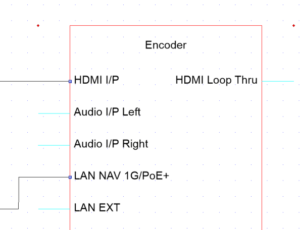
Can I formally ask for a symbol migration from your team to make sure this is done for every manufacturer symbol from the Stardraw team? Or am I still missing some other feature or setting that is causing this. For example, the screenshot is a stardraw provided symbol for an Extron NAV encoder.

Also, apologies if replying to an old topic is verboten!
Thanks for the great software otherwise though.
Edit: I just re-read the OP and realized I had not been using the align to grid feature. I found that for almost all the Strawdraw provided symbols aligning to bottom fixed the grid alignment issue. I should now be able to manage custom line paths much more easily! It is still a little difficult using objects with a single SKU that represent two separate distinct blocks (like some extenders). But this is just a single SKU (x6) on this first run on the software.
|
By Rob Robinson - 7/3/2025 6:51:01 AM
All Stardraw symbols are drawn to align to the grid 'out of the box' assuming they are inserted into the drawing with Snap to Grid ON.
If you have moved a symbol with Snap to Grid OFF, or otherwise managed to cause it to fall off the grid, you should select the symbol(s), rightclick and choose Align to Grid | Symbol Origins (do not use Align to Grid | Bottoms as this will be ineffective, even destructive, in many cases). Only by aligning Symbol Origins to the grid (shortcut: Ctrl+Alt+O) can you be sure the symbol is correctly positioned relative to the grid.
With regard to compound symbols (where one SKU includes multiple components) you can use the Unlock Cursor to move components relative to each other. Be extremely careful when using the Unlock Cursor and be sure to check what it can and can't be used for in the Help documentation.
|
By Adam W - 7/7/2025 11:33:16 PM
+xAll Stardraw symbols are drawn to align to the grid 'out of the box' assuming they are inserted into the drawing with Snap to Grid ON. If you have moved a symbol with Snap to Grid OFF, or otherwise managed to cause it to fall off the grid, you should select the symbol(s), rightclick and choose Align to Grid | Symbol Origins (do not use Align to Grid | Bottoms as this will be ineffective, even destructive, in many cases). Only by aligning Symbol Origins to the grid (shortcut: Ctrl+Alt+O) can you be sure the symbol is correctly positioned relative to the grid. With regard to compound symbols (where one SKU includes multiple components) you can use the Unlock Cursor to move components relative to each other. Be extremely careful when using the Unlock Cursor and be sure to check what it can and can't be used for in the Help documentation.

Seriously though, thanks the detailed response. Solving this issue will resolve most my quirks with this software so far.
Cheers!
-Adam
|
|